PULSAfeeder Hydraulic Diaphragm Metering Pumps
When a chemical metering system is designed for a hydraulically balanced reciprocating metering pump, there are several variables to consider in order to ensure proper system operation and sound pump hydraulics. Process fluid properties to consider are vapor pressure, specific gravity and viscosity, Some other variables that contribute to reciprocating metering pump applications are system suction pressure at the pump inlet, system backpressure at the pump outlet, length and diameter of system piping, and freedom from air and foreign matter. When all variables are considered and basic hydraulic principles are followed, the installation and operation of a reciprocating metering pump will be successful. This technical guide is designed to provide a brief description and some general guidelines for applications of hydraulically balanced reciprocating metering pumps.
Checklist of difficult conditions:
1. Piping with excessive fittings, valves, bends.
2. Suction lift or low suction head.
3. Undersized piping on either suction or discharge.
4. Dissolved gases in product pumped; unusually high vapor pressure.
5. Pumping near the required net positive suction head. (NPSHR)
6. Product specific gravity unusually high.
7. High product viscosity.
8. Long suction or discharge lines.
9. Pumping downhill – suction pressure higher than discharge pressure.
10. Pumping at unusually high or low temperatures.
11. Solids content or slurry. (Pipe size important to minimize settling.)
12. Outdoor installation in cold climate.
13. Changing elevations in suction or discharge lines. (Air traps cause problems)
Metering Pump Characteristics:
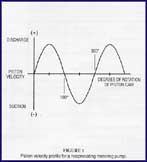
Most centrifugal and rotary pumps have steady state flow characteristic. Under normal conditions there is very little change in the velocity of the fluid pumped. That is not the case with reciprocating metering pumps, which cause the fluid to experience peak velocities and accelerations in both the suction and discharge lines. With these pumps, the fluid is initially at rest (0° of piston cam rotation, refer to Figure 1) and fluid velocity and acceleration are both zero.

Figure 1
The fluid is accelerated during the discharge cycle through peak velocity at 90° of piston cam rotation. Similarly, the suction cycle begins at rest (180° piston cam rotation) and the fluid is accelerated through peak velocity at 270° rotation. The inertial force required to initiate flow for both pumping cycles is of major significance. Because of these unique flow conditions, common to all reciprocating type metering pumps, special consideration is required of all factors that will affect pump performance.
All piping should include:
1. Shut-off valves on suction and discharge lines that open to full pipe diameter. (Ball valves are preferred.) The use of regulating valves is not recommended. (Regulating valves include needle, diaphragm, globe, and gate valves.
2. Unions or flanges on suction and discharge piping.
3. An inlet strainer if the product is not a slurry.
4. Hangers and straps to support piping.
5. Materials that are not affected by product corrosion or galvanic corrosion.
Welding pipe nipples or pipe to valve housings is not recommended.
Suction Head Requirements:
All reciprocating metering pumps require a net positive suction head (NPSHR) as shown in Table 1. The NPSHR is defined as the pressure required above the absolute vapor pressure of the process is required at the suction port of the pump throughout the entire pump stroking cycle in order to prevent cavitation of the process fluid within the reagent head. The NPSHR is one of the requirements necessary to assure metering accuracy.
 Table 1
The net positive suction head available (NPSHA) must be greater than the NPSHR. The NPSHA of any given system is calculated as follows for comparison to the NPSHR as shown in Table 1.
![]() Equation 1
Equation 1
For fluid viscosity below 50 centipoise.
 Equation 2
For fluid viscosity above 50 centipoise.
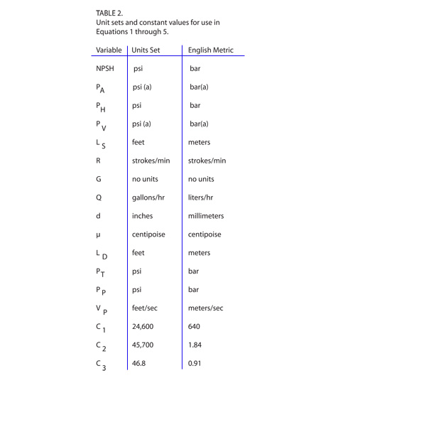
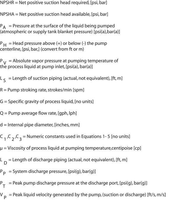
The variables used in Equations 1 through 5 must be in the units shown in Table 2 for the constants listed below to be used correctly.
NOTE: If piping sizes vary throughout the suction line, different additive values may be used for the pressure losses attributed to the liquid’s acceleration and deceleration. Use the last term of Equation 1 or 2 as many times as needed in the equation to adjust for different lengths of different pipe diameters in the suction line. (Everything but the pipe length and diameter will stay the same in the equation.)
Table 2
 |
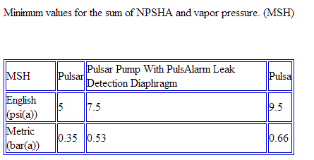
All reciprocating metering pumps also require that a minimum absolute pressure, minimum suction head (MSH), be maintained at the pump inlet throughout the pumping cycle to ensure a stable hydraulic system and proper pump operation. The sum of the NPSHA and the vapor pressure (PV) must be greater than the values shown in Table 3.
Table 3
 The system backpressure must exceed the suction pressure by at least 5 psi (0.35 bar) in order to prevent flow-through, however it must not exceed the rate discharge pressure of the pump. Flow-through can be defined as the process liquid flowing from a higher pressure to a lower pressure (downhill pumping), which attributes to pump failure and undesired flow at pump shutdown. If the system back pressure is not at least 5 psi (0.35 bar) greater than the suction pressure, a backpressure valve must be installed in the discharge piping. To calculate the system’s total backpressure use Equation 3 or 4.
![]() Equation 3
Equation 3
For fluid viscosity below 50 centipoise.
 Equation 4
For fluid viscosity above 50 centipoise.
Fluid Velocity
Fluid velocity is often used to determine the correct pipe size for an application. Since the fluid velocity generated by a metering pump varies throughout each stroke of the pump, piping must be sized and based on the peak fluid velocity and not the average fluid velocity. The peak fluid velocity generated by a positive displacement metering pump and be calculated using the following formula:
![]() Equation 5
Equation 5
Peak fluid velocity for a reciprocating metering pump. C3 values can be found in Table 2.
Pulsation Dampeners
A pulsation dampener is a pneumatically charged diaphragm within a chamber that continuously stores energy carried in the acceleration of the pumped fluid. When a PULSAtrol is used on the suction side of a metering pump, it will improve suction pressure conditions by reducing the pressure losses associated with the acceleration of the fluid. On the discharge side it will protect sensitive equipment from pulsating flow spikes, and will translate pulsating flow to nearly linear flow by reducing the peak flow and pressure generated by the metering pump. Regardless of which side of the pump the PULSAtrol is to be used on, it should always be installed as close to the pump as possible in order to reduce the length of pipe in which pulsating flow occurs.
In many installations, the diameter of costly piping can be reduced by incorporating a PULSAtrol on both suction and discharge lines. Installing a dampener can also reduce cost by allowing the use of a smaller faster stroking pump as opposed to a larger, more costly, slower stroking pump.
When a PULSAtrol pulsation dampener is used, the length of piping (LS or LD) in Equations 1 through 4 becomes the distance between the pump and the pulsation dampener. For the remainder of the piping, uniform flow friction losses can be used since the flow is now constant and not pulsating for this distance of piping. (These losses can be found in any standard friction loss table based on Darcy’s formula.) The standard friction losses must also be subtracted from the NPSHA or backpressure calculations (Equations 1 through 4).
Figure 2 – Nomenclature


Example Calculation
66° Be sulfuric acid (93%) has a specific gravity of 1.83, a viscosity of 25 cps, and a vapor pressure 0.01 psia (0 bar(a)). This product is to be metered at a flow rate of 240 GPH (908.4 LPH) to a system pressure of 100 psig (6.9 bar). The installation is at sea level and the supply tank is open to atmosphere. The proposed suction piping layout is 20 feet (6.1 meters) of 1.61 inch (40.9mm) inside diameter pipe. The proposed PULSA Series pump has a stroking rate of 58 spm.
Is 4 feet (1.22m) of suction head sufficient for proper pump operation at the above listed conditions?
Solution
The NPSHR as shown in Table 1 is 5 psi (0.35 bar) for a PULSA Series pump. Calculate the NPSHA of the system as mentioned using Equation 1, since the viscosity is less than 50 centipoise.
 Figure 3
First calculate PH:
PH[psi] = feet of fluid X (1 psi/(2.31 feet of H2O)) X G
PH = 4 feet X 0.433 X 1.83 = 3.17 psi
or
PH[m] = 1.22 X (1 bar/(10.21m of H2O)) X 1.83 = 0.22 bar
Use C1 from Table 2, and 14.7 psia (1.01bar) for atmospheric pressure at sea level.
Since NPSHA is greater than NPSHR, the system has adequate suction conditions to prevent process fluid cavitation within the reagent head.
Since NPSHA + PV = 9.91 psia (0.68 bar) which is greater than the 9.5 psia (0.66 bar) requirement shown in Table 3 for a PULSA Series pump, the pump’s hydraulic system will operate in a stable condition.