System curves are performance curves of piping systems. They are graphical representations of the energy required to move a given flow rate through a piping system and are used to identify some of the necessary characteristics of the system’s pump. The required energy is plotted on the vertical axis and is given in terms of head. The capacity is plotted along the horizontal axis and is given in cubic meters per hour or liters per second. System curves are the sum of the static suction and discharge heads and the friction head losses of the piping system. Normally, the static heads of a system remain fairly constant and are independent of capacity, but friction head losses increase approximately as the square of the velocity of the liquid passing through the system. The friction head losses give system curves an upward curving shape as the capacity increases.
 |
 |
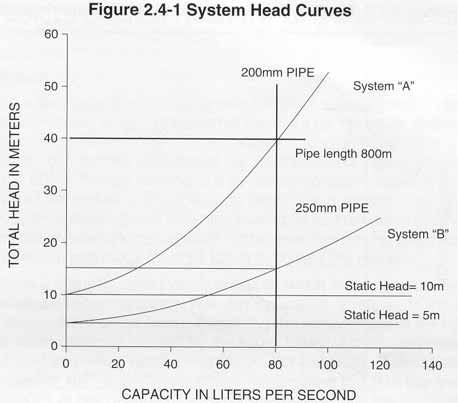
Figure 2.4-1 shows examples of two system curves. In this figure, the system curves for two different piping systems have been plotted on the same graph. In system “A”, there is a static head of 10 meters and a pipeline consisting of 800 meters of 200 mm pipe. The friction losses at various capacities have been calculated and plotted on this graph and these points have been connected to form a smooth curve. In system “B”, the static head has been reduced to 5 meters and the system contains 800 meters of 250 mm pipe. The friction losses at various capacities have been plotted for this system and connected with a smooth curve. Because the velocity is lower in the 250 mm pipe for a given capacity, the friction losses are less and system curve “B” has a more gradual rise than curve “A”.
Figure 2.4-1 can be used to compare system A with system B and such comparisons are done by piping designers to determine the most economical system layout. If a capacity of 80 liters per second is selected, the curve for system “A” shows that 40 meters of head will be required to deliver this flow. If system “B” is selected, only 15 meters of head is required to deliver the same capacity. System “B” results in a pump that runs at a lower speed, uses less power, and will cost less to operate. However, this reduction in operating expense may be more than offset by the increased capital expense of the larger, more costly pipeline. The larger pipe of system “B” may also result in a pipeline velocity that is too low to keep the solids in the slurry in suspension.
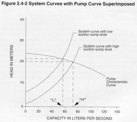
A given system may have more than one system curve. This typically results from a change in static head as the pump operates through a normal cycle. An example would be a pump transferring a liquid from one location to another. As the pump empties the suction supply sump or tank, the liquid level will drop resulting in an increase in the system static head. This causes the system curve to shift upward by the amount of the increase in static head. If the pump runs at a constant speed, the shift in the system curve will make the pump deliver less flow at the higher system head. Figure 2.4-2 has a pump performance curve plotted with the system curves and shows the change in flow resulting from a change in the static system head. The amount of change in flow depends on the shape of the system curve and how much the static head has increased. Because slurry pumps usually have fairly flat performance curves, even small changes in the static system head can make significant changes to the flow rate.
Pumps always operate at the point where the system curve intersects the pump performance curve. This graphic intersection represents the capacity where the energy required to move the liquid through the piping system equals the energy transferred to the liquid by the pump. In the example given above, the pump will deliver capacity “H” when the suction sump level is high and capacity “L” when the sump level is low. When there is a change in the static head of a system during normal operation, it is necessary to plot system curves for the high and low levels and determine if the selected pump will deliver a suitable range of flows.
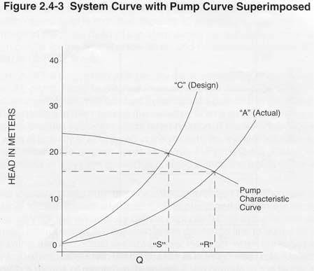
The calculation of the system curve is usually the responsibility of the system designer or purchaser of a pump. Many factors are involved in determining the system curve, and the details of the process are well covered in handbooks common in the pump industry. A number of the variables in this process are selected from a range of possible values which makes the process subject to some interpretation. If the selected friction factor is higher than what is actually encountered in the system, the system will have a calculated system curve and an actual system curve as shown in Figure 2.4-3. The higher friction factor chosen results in a system curve that is steeper than the actual curve which may cause problems.
 |
 |
Figure 2.4-3 shows a pump performance curve intersected by two system curves, the calculated curve “C” and the actual curve “A”. The pump and system are expected to operate at capacity “S” but will actually deliver capacity “R”. In systems that pump non-abrasive liquids, control valves are installed in the discharge line to adjust for differences between the calculated and actual system curves. However, when abrasives are being handled, control valves are seldom used because of the high wear rate. Unless the pump is equipped with a means of regulating its speed, it will operate at the higher capacity. This may allow the pump to periodically drain the sump if the capacity is greater than the filling rate of the sump. This results in surging that will sharply decrease the pump’s wear life and can damage other system components. It may also have adverse effects on the process being performed by the system.
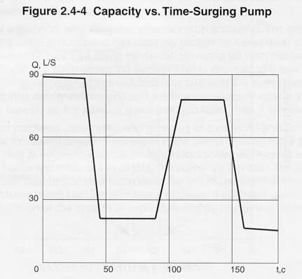
Figure 2.4-4 is a graph of what happens when a pump is surging. The graph is plotted from test data of a surging pump and has capacity plotted on the vertical axis and time plotted on the horizontal axis. The pump starts out delivering 90 liters per second, and as the sump level drops to a point where the suction inlet is exposed, the flow rate rapidly decreases. The pump operates at this reduced flow rate until the sump level fills to the point the suction inlet is fully submerged and the flow increases to nearly the original value. The cycle repeats as the sump is again emptied faster than it is replenished.
There are other problems associated with pumping at a capacity greater than the design point. The increased flow rate will result in the pump drawing more power than expected which may overload the motor. Increased capacities will require a higher net positive suction head, and if it is not available, the pump will cavitate. The pump could also wear out faster than anticipated because of the increased internal velocities caused by the greater volume being handled. For these reasons, it is always good practice to allow for safe operation of the system at capacities slightly higher than the design flow.